

Appearance
Excitation System (AC1A)
IEEE 421.5 Type AC1A excitation system / automatic voltage regulator: a field-controlled alternator exciter feeding the generator field through non-controlled (diode) rectifiers, implemented to the AC1C block diagram, which accepts AC1A data unchanged. Sense the terminal voltage Vt, form the voltage error against the reference, shape it with a lead-lag (1+sTC)/(1+sTB), amplify with the regulator KA/(1+sTA) bounded by [VAMIN, VAMAX], pass the UEL / OEL take-over gates and the exciter field-voltage limit [VRMIN, VRMAX], and drive the rotating exciter 1/(sTE) whose field current VFE = VE*(KE + SE(VE)) + KDIfd carries saturation and armature demagnetization. The output EFD = VEFEX(KCIfd/VE) carries the rectifier regulation drop. Rate feedback KFs/(1+sTF) from VFE, optional PSS / UEL / OEL inputs (UEL / OEL summed or through take-over gates), AC1C's VEMIN / VFEMAX exciter limits, and an optional external Vref override. Pairs with the synchronous machine for bumpless load-flow initialization. Also known as AC1C, ESAC1A and EXAC1.
Category: Control / Excitation
Overview
The Type AC1A excitation system is the IEEE Std 421.5 model of a field-controlled alternator-rectifier exciter: a rotating alternator on the generator shaft feeds the field through non-controlled (diode) rectifiers, and the voltage regulator controls the alternator's own field. The regulator's supply does not depend on the generator terminals, so a close-in fault does not collapse the forcing, but the rotating exciter's field time constant makes the response far slower than a static bridge. Brushless exciters are the typical application.
This component implements the block diagram of the newer Type AC1C model (IEEE Std 421.5-2016, Figures 8 and 9). AC1C accepts AC1A data unchanged once its two extra exciter limits sit at their AC1A values (VEMIN = 0, VFEMAX = 99, the defaults). The model senses the machine terminal voltage Vt and the field current Ifd, and outputs the field voltage EFD that wires into the synchronous machine's Efd input. With the load-flow auto-initialization (below) the exciter starts on its operating point, so a study begins in steady state with no excitation transient.
AC1A is also catalogued as AC1C, ESAC1A and EXAC1 in some libraries.
Block diagram
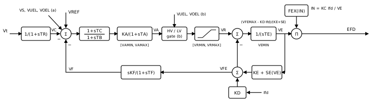
Signal flow, block by block (all quantities per-unit,
- Terminal-voltage transducer —
- Voltage error —
where the superscript marks a limiter connected at location (a) (see Alternate input locations). vref0, unless the optional external Vref input is wired, which overrides it.
Lead-lag —
; both time constants zero is a pass-through. Regulator —
, held inside by a non-windup limit. Take-over gates and exciter field-voltage limit — an HV gate
and an LV gate (location b), then . AC1C calls these limits / . Rotating exciter —
- Rectifier regulation —
- Rate feedback —
, taken from the exciter field current and zero in steady state. It is off when or .
The rotating exciter
The exciter field current
, the unsaturated field requirement. , saturation. is the two-point quadratic fit through and , evaluated on the exciter output . Set both factors to 0 for an unsaturated exciter. , armature reaction: the generator's field current loads the alternator and demagnetizes it, so holding the same takes more exciter field. A rise in therefore lowers over until the regulator catches up.
The integrator is held inside two non-windup limits:
: the diodes cannot reverse the exciter output, so AC1A uses 0. , which keeps . This is AC1C's instantaneous exciter field-current limit. Leave (never binds) when an explicit over-excitation limiter model protects the field, so the two do not act together.
With
Rectifier regulation
The diode bridge's commutating reactance drops the output as the field current rises. IEEE Std 421.5 Annex D expresses the drop through the normalized load
| Mode | Range | |
|---|---|---|
| 1 | ||
| 2 | ||
| 3 | ||
| — |
The drop acts instantly:
Alternate input locations
The PSS input VS always adds at the voltage error. Each limiter input can connect at one of two points; pick it on the Aux Inputs tab after enabling the input:
| Input | (a) | (b) |
|---|---|---|
| VUEL (under-excitation limiter) | added to the voltage error | HV gate on the regulator output |
| VOEL (over-excitation limiter) | added to the voltage error | LV gate on the regulator output |
Location (b) is the AC1A placement and the default; (a) is the AC1C addition, and the placement of the older EXAC1 model. A summation input that is enabled but unwired reads zero; a take-over gate whose input is unwired is a pass-through.
Per-unit convention
Field voltage EFD is in the non-reciprocal per-unit system: Efd input, Ifd output and Vt output use the same convention, so the exciter and machine plug together without scaling.
External voltage reference (Vref)
Enabling External Vref input exposes a Vref port that overrides the auto-initialized set-point. Because the port replaces the set-point, you must wire it when it is enabled: an unconnected Vref reads zero and collapses the reference. For a bumpless start, hold Vref at the auto-computed vref0 (shown on the Initialization tab) through
Load-flow auto-initialization
After the load flow solves, the apply pass back-calculates the set-point and the state seeds so every derivative in the diagram is zero at
- Pairing is wire-traced. The initializer follows the
EFDwire (throughGoTo/Fromlabels) to the unique synchronous machine whoseEfdit feeds. Fan-out to several machines, or an intermediate block in the path, skips initialization with a warning. - The exciter voltage comes from the rectifier inverse. At rest the machine reports
, its field voltage. Each mode inverts in closed form,
and the initializer keeps the one whose own
- The set-point balances the loop. With the lead-lag at DC gain 1, the rate feedback washed out and the gates idle,
Initialization is skipped when no
These quantities populate VREF, VC(0), VE(0) and IFD(0) on the Initialization tab. On the first time step the model also uses Vt and Ifd signals, so the regulator does not kick at
Wiring
- Vt ← the synchronous machine's
Vtoutput. - EFD → the synchronous machine's
Efdinput. - Ifd ← the machine's field-current output (appears when
KC != 0orKD != 0). - Optionally VS / VUEL / VOEL ← a stabilizer or limiter model, at the location chosen on the Aux Inputs tab.
- Optionally Vref ← an external set-point source.
Enable Monitor EFD / VC / VA / VE / VFE on the Monitoring tab to record the field voltage, the sensed voltage, the regulator output, the exciter output and the exciter field current.
When to use something else
- A static (bus-fed thyristor) exciter: use Type ST1A, whose ceiling follows the terminal voltage and which responds almost instantly.
- A high-initial-response alternator exciter modeled as a fast regulator: use Type AC4A.
- A rotating DC commutator exciter: use Type DC1A.
Ports
| Port | Kind | Signal | Notes |
|---|---|---|---|
Vt | Control input | Real | |
Ifd | Control input | Real | Shown when KC is not 0 or KD is not 0 |
Vref | Control input | Real | Shown when External Vref input (Vref) is On |
VS | Control input | Real | Shown when PSS input (VS) is On |
VUEL | Control input | Real | Shown when UEL input (VUEL) is On |
VOEL | Control input | Real | Shown when OEL input (VOEL) is On |
EFD | Control output | Real |
Parameters
Regulator
| Parameter | Type | Default | Units | Description | ID |
|---|---|---|---|---|---|
| TR | Number | 0 | s (also ms) | Terminal-voltage transducer (sensing) time constant 1/(1+sTR). TR = 0 senses Vt directly. | TR |
| TC | Number | 0 | s (also ms) | Lead-lag numerator (lead) time constant of (1+sTC)/(1+sTB). Leave TB = TC = 0 to bypass. | TC |
| TB | Number | 0 | s (also ms) | Lead-lag denominator (lag) time constant of (1+sTC)/(1+sTB). With TB = 0 the block is a pure lead 1+sTC (or a pass-through when TC = 0 too). | TB |
| KA | Number | 400 | — | Voltage-regulator gain (pu exciter field voltage per pu voltage error). | KA |
| TA | Number | 0.02 | s (also ms) | Voltage-regulator time constant of the KA/(1+sTA) block. TA = 0 makes the regulator a pure gain. | TA |
| VAMAX | Number | 14.5 | — | Upper non-windup limit on the regulator output VA (pu). | VAMAX |
| VAMIN | Number | -14.5 | — | Lower non-windup limit on the regulator output VA (pu). | VAMIN |
| KF | Number | 0.03 | — | Rate-feedback gain of the sKF/(1+sTF) stabilizing loop, taken from the exciter field current VFE. | KF |
| TF | Number | 1 | s (also ms) | Rate-feedback time constant. The feedback is disabled when KF = 0 or TF = 0. | TF |
Exciter
| Parameter | Type | Default | Units | Description | ID |
|---|---|---|---|---|---|
| VRMAX | Number | 6.03 | — | Maximum exciter field voltage (pu): the upper limit on VR after the take-over gates. Called EFEmax in AC1C. | VRMAX |
| VRMIN | Number | -5.43 | — | Minimum exciter field voltage (pu). Called EFEmin in AC1C. | VRMIN |
| TE | Number | 0.8 | s (also ms) | Exciter field time constant of the 1/(sTE) integrator. TE = 0 makes the exciter algebraic: VE settles within the step so that VFE = VR. | TE |
| KE | Number | 1 | — | Exciter field proportional constant: the unsaturated slope of the exciter field current VFE against the exciter output VE. | KE |
| E1 | Number | 4.18 | — | Exciter output voltage VE at the first saturation point (pu). | E1 |
| SE(E1) | Number | 0.1 | — | Exciter saturation factor SE(E1) at E1. Set SE1 = SE2 = 0 for an unsaturated exciter. | SE1 |
| E2 | Number | 3.14 | — | Exciter output voltage VE at the second saturation point (pu). | E2 |
| SE(E2) | Number | 0.03 | — | Exciter saturation factor SE(E2) at E2. | SE2 |
| KC | Number | 0.2 | — | Rectifier loading factor, proportional to the commutating reactance. EFD = VE * FEX(KC*Ifd/VE). When KC or KD is non-zero a field-current input Ifd appears. | KC |
| KD | Number | 0.38 | — | Demagnetizing factor, a function of the exciter alternator reactances: KD*Ifd adds to the exciter field current VFE. | KD |
| VEMIN | Number | 0 | — | Lower limit on the exciter output VE (pu). 0 for the diode rectifier of AC1A; an AC1C parameter. | VEMIN |
| VFEMAX | Number | 99 | — | Upper limit on the exciter field current VFE (pu), applied as the VE ceiling (VFEMAX - KD*Ifd)/(KE + SE(VE)). 99 (never binds) reproduces AC1A; an AC1C parameter. Leave it at 99 when an OEL model protects the field. | VFEMAX |
Aux Inputs
| Parameter | Type | Default | Units | Description | ID |
|---|---|---|---|---|---|
| External Vref input (Vref) | Choice: Off / On | Off | — | Expose an external voltage-reference input port Vref. When on, a Vref port appears and OVERRIDES (replaces) the regulator setpoint: the wired signal is used as VREF instead of the internal, auto-initialized vref0. You must wire it - an enabled but unconnected Vref reads 0 and collapses the reference. Leave off to use the auto-computed vref0. | enable_vref |
| PSS input (VS) | Choice: Off / On | Off | — | Expose the stabilizer input VS for a power system stabilizer. VS is added at the voltage-error summing junction. | enable_pss |
| UEL input (VUEL) | Choice: Off / On | Off | — | Expose the under-excitation limiter input VUEL. Where it enters is set by UEL location. | enable_uel |
| UEL location | Choice: Summation at voltage error (a) / Take-over at regulator output (b) | Take-over at regulator output (b) | — | Where VUEL enters: added at the voltage-error junction (a), or through an HV (take-over) gate on the regulator output (b), the AC1A placement. | uel_location |
| OEL input (VOEL) | Choice: Off / On | Off | — | Expose the over-excitation limiter input VOEL. Where it enters is set by OEL location. | enable_oel |
| OEL location | Choice: Summation at voltage error (a) / Take-over at regulator output (b) | Take-over at regulator output (b) | — | Where VOEL enters: added at the voltage-error junction (a), or through an LV (take-over) gate after the HV gate (b), the AC1A placement. | oel_location |
Monitoring
| Parameter | Type | Default | Units | Description | ID |
|---|---|---|---|---|---|
| Monitor EFD | Choice: Off / On | Off | — | Record the field voltage EFD (pu) as a named observable. | measure_efd |
| Monitor VC | Choice: Off / On | Off | — | Record the sensed (transduced) terminal voltage VC (pu) as a named observable. | measure_vc |
| Monitor VA | Choice: Off / On | Off | — | Record the regulator output VA (pu, after its [VAMIN, VAMAX] limit) as a named observable. | measure_va |
| Monitor VE | Choice: Off / On | Off | — | Record the exciter output voltage VE (pu) as a named observable. | measure_ve |
| Monitor VFE | Choice: Off / On | Off | — | Record the exciter field current VFE (pu) as a named observable. | measure_vfe |
Signal Names
| Parameter | Type | Default | Units | Description | ID |
|---|---|---|---|---|---|
| EFD name | Text | (empty) | — | Observable name for the field voltage EFD. Blank = skip. | efd_name |
| VC name | Text | (empty) | — | Observable name for the sensed terminal voltage VC. Blank = skip. | vc_name |
| VA name | Text | (empty) | — | Observable name for the regulator output VA. Blank = skip. | va_name |
| VE name | Text | (empty) | — | Observable name for the exciter output voltage VE. Blank = skip. | ve_name |
| VFE name | Text | (empty) | — | Observable name for the exciter field current VFE. Blank = skip. | vfe_name |
Initialization
| Parameter | Type | Default | Units | Description | ID |
|---|---|---|---|---|---|
| VREF | Number | 1 | — | Voltage-regulator setpoint reference (pu). Normally computed by the load-flow auto-initialization so the regulator starts in balance; set manually only for standalone use. Ignored at run time when the external Vref input is enabled and wired (the port overrides it). | vref0 |
| VC(0) | Number | 1 | — | Initial sensed terminal voltage at t = 0 (pu). Seeds the transducer state and stands in for Vt on the first step. Normally set by the load-flow auto-initialization to the machine terminal-voltage magnitude. | vc_init |
| VE(0) | Number | 1 | — | Initial exciter output voltage VE at t = 0 (pu): the value whose rectified output VE * FEX(KC*Ifd/VE) is the machine's field voltage. Seeds the exciter integrator; the regulator and rate-feedback states follow from it. Normally set by the load-flow auto-initialization. | ve_init |
| IFD(0) | Number | 1 | — | Initial machine field current at t = 0 (pu, equal to the field voltage at rest). Seeds the exciter field current and stands in for Ifd on the first step. Normally set by the load-flow auto-initialization. | ifd_init |
Observables
| Default name | Kind | Recorded when | Description | ID |
|---|---|---|---|---|
| set by EFD name | Signal | Monitor EFD is on | Field voltage EFD = VEFEX(KCIfd/VE) (pu, non-reciprocal) commanded to the machine's Efd input. | EFD |
| set by VC name | Signal | Monitor VC is on | Sensed (transduced) terminal voltage VC (pu) after the 1/(1+sTR) transducer. | vc |
| set by VA name | Signal | Monitor VA is on | Regulator output VA (pu) after its [VAMIN, VAMAX] limit, before the take-over gates. | va |
| set by VE name | Signal | Monitor VE is on | Exciter output voltage VE (pu): the exciter integrator state, before the rectifier regulation. | ve |
| set by VFE name | Signal | Monitor VFE is on | Exciter field current VFE = VE*(KE + SE(VE)) + KD*Ifd (pu). | vfe |