

Appearance
Turbine-Governor (GGOV1)
GGOV1 general-purpose turbine-governor (IEEE PES-TR1). A speed-governing prime mover for the synchronous machine: it senses rotor speed ω and electrical power Pe and drives the machine's mechanical-torque input Tm. The full model includes a PID speed governor with selectable droop feedback (electrical power, valve stroke, governor output, or isochronous), a fuel-valve actuator with rate and position limits, a turbine with gain Kturb, lead-lag (1+sTc)/(1+sTb) and an optional transport delay Teng, plus two supervisory limiters — an acceleration limiter and a load (fuel-flow) limiter — combined with the governor through a low-value select so the most restrictive fuel command wins. Optional supervisory MW set-point control adjusts the load reference. Mechanical power Pmech = Kturb·(Wf − Wfnl) is converted to torque Tm = Pmech/ω at the output. Pairs with the synchronous machine for bumpless load-flow initialization: wire ω from the machine's speed output and Pe from its electrical-power output, and Tm back to the machine's Tm input. The right-edge ω / Pe (in) and Tm (out) ports line up with the machine's left-edge speed / Pe (out) and Tm (in) ports for a direct connection.
Category: Control / Governor
Overview
The GGOV1 general-purpose turbine-governor (IEEE PES-TR1, Dynamic Models for Turbine-Governors in Power System Studies) is the prime mover for a synchronous machine. It senses the rotor speed ω (and, for electrical-power droop, the machine's electrical-power output Pe) and drives the machine's mechanical-torque input Tm so the unit shares load and regulates frequency the way a real governed turbine does.
GGOV1 is deliberately broad: with one parameter set it represents a gas turbine, and with others a diesel or a simple steam unit. It pairs a PID speed governor (with selectable droop feedback) and a fuel-valve actuator with two supervisory limiters — an acceleration limiter and a load (fuel-flow) limiter — combined through a low-value select so the most restrictive fuel command always wins. With the optional load-flow auto-initialization (below) the whole speed-governor → turbine loop starts on its operating point, so a study begins in steady state with no torque transient.
Block diagram
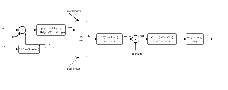
Signal flow, block by block (per-unit,
- Speed error — the governor compares the load reference to the droop feedback and the speed deviation, with a deadband and error limits,
where Rselect (see below), db/2 deadband.
- Governor PID — the fuel request from a parallel proportional-integral-derivative law,
Leave
- Acceleration limiter — an integrator that drives the fuel down when the rotor accelerates faster than
aset,
- Load (fuel-flow) limiter — a PI loop holding the measured fuel flow at or below
Ldref,
- Low-value select — the governor competes with the two limiters; the most restrictive wins,
- Fuel-valve actuator — a first-order lag with a rate limit
and a position limit ,
- Turbine — the fuel flow
( when Flag= 1, else just the valve) drives the mechanical power through a gain, a lead-lag and an optional transport delay,
- Output — mechanical power is delivered to the machine as torque,
Droop feedback (Rselect)
The permanent-droop feedback signal
Rselect | Feedback | Use |
|---|---|---|
| Electrical power (Pe) | the transduced electrical power | the usual choice — exposes the Pe input port |
| Valve stroke | the valve position | droop on actuator position |
| Governor output | the post-governor fuel request | droop on fuel demand |
| Isochronous (none) | a single unit holding system frequency (R has no effect) |
With droop, the steady speed falls by
Acceleration and load limiters
Both supervisory limiters feed the low-value select, so they only act when they would command less fuel than the governor:
- The acceleration limiter caps the rate of rotor acceleration to
aset— it protects the prime mover during a large under-frequency event by refusing to dump fuel in faster than the shaft can safely accelerate. Raiseasetwell above any expected acceleration to make it inactive. - The load limiter is the temperature / fuel-flow ceiling of a gas turbine: it holds the measured fuel flow at or below
Ldref. RaiseLdrefabove the operating fuel flow to keep it inactive.
Each limiter's integrator uses back-calculated anti-windup so it tracks the achievable fuel command instead of winding past it while the low-value select holds another path.
Per-unit convention
All power quantities — Pe, the mechanical power S rated). Tm input and Pe output use the same base, so the governor and machine plug together without any scaling. The speed ω and the deadband / droop are per-unit of synchronous speed.
Load-flow auto-initialization
The governor participates in the project's controller auto-initialization so a run starts bumpless. After the load-flow solves, the apply pass back-calculates the load reference and the integrator seeds so every derivative in the block diagram is zero at
Pairing is wire-traced. The governor declares that its
Tmoutput drives a machine shaft; the initializer follows that wire (throughGoTo/Fromlabels) to the unique synchronous machine whoseTmit feeds. If the output fans out to more than one machine, or an intermediate block sits in the path, initialization is skipped with a warning rather than guessing.The mechanical power matches the machine.
is set to the same mechanical torque the paired machine derives from its load-flow operating point (shared back-calculation), and to the machine's terminal real-power output. The fuel chain is inverted. From the steady turbine (
) the operating fuel flow, valve position and governor-output set-point are
where Rselect. The governor PI integrator, the valve, the turbine lead-lag, the transport-delay buffer and both limiter tracking states are seeded from these so the speed error is exactly zero and
These quantities populate Pref, Pmech(0) and Pe(0) on the Initialization tab. You normally never type them by hand; set them only when using the governor standalone (driven by a constant speed), in which case choose them to start flat.
Wiring
- speed (ω) ← the synchronous machine's
speedoutput (pu). - Pe ← the synchronous machine's
Peoutput (electrical power, pu). Present only whenRselect= Electrical power. - Tm → the synchronous machine's
Tminput (mechanical torque, pu).
The governor sits to the left of the machine: its right-edge ω / Pe (in) and Tm (out) ports line up with the machine's left-edge speed / Pe (out) and Tm (in) ports, so the three wires draw straight across. Enable Monitor Pmech / valve / fuel request / measured power on the Monitoring tab to record those signals as named channels for plotting.
When to use something else
- A fixed mechanical drive (no speed governing): leave the machine's
Tmunwired and use its constanttm0fallback instead of a governor — appropriate when you only study the electrical / excitation side and the prime mover is assumed stiff. - Detailed multi-shaft / hydro / boiler dynamics: GGOV1 is a general single-shaft model; a turbine with significant penstock-water-column (hydro), boiler-pressure or cross-compound dynamics needs a model tailored to that plant. GGOV1 covers the gas / diesel / simple-steam cases that dominate frequency-stability studies.
Ports
| Port | Kind | Signal | Notes |
|---|---|---|---|
speed | Control input | Real | |
Pe | Control input | Real | Shown when Droop feedback is Electrical power (Pe) |
Tm | Control output | Real |
Parameters
Governor
| Parameter | Type | Default | Units | Description | ID |
|---|---|---|---|---|---|
| Droop feedback | Choice: Electrical power (Pe) / Valve stroke / Governor output / Isochronous (none) | Electrical power (Pe) | — | Signal fed back through the permanent droop R to form the speed-governing characteristic. Electrical power uses the machine's Pe output (the Pe input port appears); valve stroke and governor output use internal signals; isochronous removes the droop feedback (R has no effect) for a single unit holding frequency. | Rselect |
| R (droop) | Number | 0.04 | — | Permanent speed droop (pu). The steady speed/load characteristic: a 0.04 (4%) droop drops speed 4% from no-load to full-load. Ignored when the droop feedback is Isochronous. | R |
| Tpelec | Number | 1 | s (also ms) | Electrical-power transducer time constant 1/(1+sTpelec) on the Pe input (used for the electrical-power droop feedback). | Tpelec |
| Kpgov | Number | 10 | — | Governor proportional gain. | Kpgov |
| Kigov | Number | 2 | — | Governor integral gain. The integral term removes steady speed error (within the droop characteristic). | Kigov |
| Kdgov | Number | 0 | — | Governor derivative gain. Set 0 to disable the derivative term (PI control). | Kdgov |
| Tdgov | Number | 1 | s (also ms) | Governor derivative-filter time constant of the sKdgov/(1+sTdgov) term. | Tdgov |
| maxerr | Number | 0.05 | — | Upper limit on the governor speed error (pu) entering the PID. | maxerr |
| minerr | Number | -0.05 | — | Lower limit on the governor speed error (pu) entering the PID. | minerr |
| Deadband | Number | 0 | — | Speed-error deadband (pu, total width). The governor ignores speed errors within ±db/2. Set 0 for no deadband. | db |
Actuator & Turbine
| Parameter | Type | Default | Units | Description | ID |
|---|---|---|---|---|---|
| Tact | Number | 0.5 | s (also ms) | Fuel-valve actuator time constant 1/(1+sTact). | Tact |
| Vmax | Number | 1 | — | Maximum valve position (pu). | Vmax |
| Vmin | Number | 0.15 | — | Minimum valve position (pu). | Vmin |
| Ropen | Number | 0.1 | — | Maximum valve opening rate (pu/s). Positive. | Ropen |
| Rclose | Number | -0.1 | — | Maximum valve closing rate (pu/s). Negative. | Rclose |
| Kturb | Number | 1.5 | — | Turbine gain. Mechanical power Pmech = Kturb·(Wf − Wfnl). | Kturb |
| Wfnl | Number | 0.187 | — | No-load fuel flow (pu). The fuel needed to run the unloaded turbine at synchronous speed. | Wfnl |
| Tb | Number | 0.5 | s (also ms) | Turbine lag (denominator) time constant of the (1+sTc)/(1+sTb) block. | Tb |
| Tc | Number | 0 | s (also ms) | Turbine lead (numerator) time constant of the (1+sTc)/(1+sTb) block. Leave Tc = 0 (with Tb the dominant turbine lag) for a simple first-order turbine. | Tc |
| Teng | Number | 0 | s (also ms) | Transport delay (s) of the turbine, e^(−sTeng). Used for reciprocating (diesel) engines; leave 0 for gas / steam turbines (no delay). | Teng |
| Fuel vs speed | Choice: Proportional to speed / Independent of speed | Proportional to speed | — | Whether the fuel flow depends on speed. 'Proportional to speed' (Flag = 1) sets Wf = valve·ω (the usual gas-turbine case); 'Independent of speed' sets Wf = valve. | Flag |
| Dm | Number | 0 | — | Mechanical damping / speed-sensitivity of the turbine power: Pmech is reduced by Dm·(ω − 1). Set 0 to disable. | Dm |
Load Limiter
| Parameter | Type | Default | Units | Description | ID |
|---|---|---|---|---|---|
| Ldref | Number | 1 | — | Load limiter reference (pu fuel flow). The load limiter holds the fuel flow at or below this value; raise it well above the operating fuel flow to keep the limiter inactive. | Ldref |
| Kpload | Number | 2 | — | Load limiter proportional gain. | Kpload |
| Kiload | Number | 0.67 | — | Load limiter integral gain. | Kiload |
| Tfload | Number | 3 | s (also ms) | Fuel-flow measurement lag 1/(1+sTfload) feeding the load limiter. | Tfload |
Acceleration Limiter
| Parameter | Type | Default | Units | Description | ID |
|---|---|---|---|---|---|
| aset | Number | 0.01 | — | Acceleration limiter set-point (pu/s). When the rotor acceleration dω/dt exceeds aset the limiter reduces fuel through the low-value select; raise aset to effectively disable it. | aset |
| Ka | Number | 10 | — | Acceleration limiter integrator gain. | Ka |
| Ta | Number | 0.1 | s (also ms) | Acceleration measurement (derivative-filter) time constant. | Ta |
Supervisory (MW)
| Parameter | Type | Default | Units | Description | ID |
|---|---|---|---|---|---|
| Kimw | Number | 0 | — | Supervisory MW-controller integral gain. When non-zero, a slow outer loop adjusts the load reference Pref to hold the electrical power at Pmwset. Set 0 to disable (the load reference stays at its initialized value). | Kimw |
| Pmwset | Number | 0 | — | Supervisory MW set-point (pu on the machine base). Used only when Kimw ≠ 0. | Pmwset |
Monitoring
| Parameter | Type | Default | Units | Description | ID |
|---|---|---|---|---|---|
| Monitor Pmech | Choice: Off / On | Off | — | Record the mechanical power Pmech (pu) as a named observable. | measure_pmech |
| Monitor valve | Choice: Off / On | Off | — | Record the fuel-valve position (pu) as a named observable. | measure_valve |
| Monitor fuel request | Choice: Off / On | Off | — | Record the post-low-value-select fuel request fsr (pu) as a named observable. | measure_fsr |
| Monitor measured power | Choice: Off / On | Off | — | Record the transduced electrical power Pmeas (pu) as a named observable. | measure_pmeas |
Signal Names
| Parameter | Type | Default | Units | Description | ID |
|---|---|---|---|---|---|
| Pmech name | Text | (empty) | — | Observable name for the mechanical power Pmech. Blank = skip. | pmech_name |
| Valve name | Text | (empty) | — | Observable name for the valve position. Blank = skip. | valve_name |
| fsr name | Text | (empty) | — | Observable name for the fuel request fsr. Blank = skip. | fsr_name |
| Pmeas name | Text | (empty) | — | Observable name for the measured electrical power. Blank = skip. | pmeas_name |
Initialization
| Parameter | Type | Default | Units | Description | ID |
|---|---|---|---|---|---|
| Pref | Number | 0 | — | Load reference (pu). Normally computed by the load-flow auto-initialization (Pref = R·Pfb at the operating point) so the governor starts in balance; set manually only for standalone use. | pref0 |
| Pmech(0) | Number | 0 | — | Initial mechanical power at t = 0 (pu, = the machine's mechanical torque at synchronous speed). Seeds the turbine, valve and governor integrator. Normally set by the load-flow auto-initialization from the paired machine's operating point. | pmech0 |
| Pe(0) | Number | 0 | — | Initial electrical power at t = 0 (pu on the machine base). Seeds the power transducer. Normally set by the load-flow auto-initialization to the machine's terminal real-power output. | pe0 |
Observables
| Default name | Kind | Recorded when | Description | ID |
|---|---|---|---|---|
| set by Pmech name | Signal | Monitor Pmech is on | Turbine mechanical power Pmech (pu) = Kturb·(Wf − Wfnl) after the turbine lead-lag and transport delay, less Dm·(ω − 1). | pmech |
| set by Valve name | Signal | Monitor valve is on | Fuel-valve position (pu) after the actuator rate and position limits. | valve |
| set by fsr name | Signal | Monitor fuel request is on | Fuel set request fsr (pu) — the low-value select of the governor, acceleration-limiter and load-limiter outputs that drives the actuator. | fsr |
| set by Pmeas name | Signal | Monitor measured power is on | Transduced electrical power Pmeas (pu) after the 1/(1+sTpelec) power transducer (the droop feedback when Rselect = electrical power). | pmeas |