

Appearance
Turbine-Governor (IEEEG1)
IEEEG1 IEEE Type 1 speed-governing model for steam turbines (IEEE PES-TR1), the steam governor PES-TR1 recommends. It senses rotor speed ω and drives the synchronous machine's mechanical-torque input Tm. The speed deviation passes a speed relay K(1+sT2)/(1+sT1), where K is the reciprocal of the droop; the valve servo integrates (Pref − relay output − GV)/T3 within the valve rate limits [Uc, Uo] and the position limits [PMIN, PMAX]; and the valve position GV feeds four cascaded turbine stages 1/(1+sT4) … 1/(1+sT7) whose outputs, weighted by the high-pressure power fractions K1, K3, K5 and K7, sum to the mechanical power Pm, delivered as torque Tm = Pm/ω. The model drives a single shaft: K2, K4, K6 and K8, the low-pressure fractions of a cross-compound unit's second shaft, are kept for data exchange but not used. Pairs with the synchronous machine for bumpless load-flow initialization. The right-edge ω (in) and Tm (out) ports line up with the machine's left-edge speed (out) and Tm (in) ports for a direct connection.
Category: Control / Governor
Overview
The IEEEG1 turbine-governor is the IEEE Type 1 speed-governing model for steam units, the one IEEE PES-TR1 recommends for steam turbines in grid studies. Compared with the minimal TGOV1 it adds valve rate limits, a speed relay with lead-lag shaping, and four turbine stages (steam chest, reheater, crossover and a second reheater), each contributing its own fraction of the shaft power.
It senses the machine rotor speed ω and outputs the mechanical torque Tm that drives the machine. With the load-flow auto-initialization (below) the governor starts on its operating point, so a study begins in steady state with no torque transient.
IEEEG1 assumes constant steam pressure and temperature. It suits frequency deviations of a few tenths of a percent; boiler dynamics and coordinated plant controls are outside its scope.
Block diagram
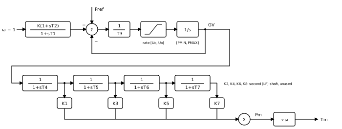
Signal flow, block by block (all quantities per-unit on the machine rating,
- Speed relay —
where
- Valve servo — the valve position
is the integral of
held inside
- Turbine stages — four cascaded lags
for the steam chest, the reheater, the crossover and a second reheater. A zero time constant bypasses its stage; a single-reheat unit leaves
- Mechanical power and torque —
Normally
In steady state a speed change
as long as the valve stays inside its position limits.
One shaft: the low-pressure fractions
The standard model can drive a cross-compound unit, whose high- and low-pressure turbines spin two separate generators:
This component drives one shaft, the usual tandem-compound unit.
A PSS/E IEEEG1 record whose JBUS names a second machine is a cross-compound unit; the import lists it as unsupported.
Rate limits and sign convention
Load-flow auto-initialization
After the load flow solves, the apply pass back-calculates the load reference and the valve seed so every derivative in the diagram is zero at
- Pairing is wire-traced. The initializer follows the
Tmwire (throughGoTo/Fromlabels) to the unique synchronous machine whoseTmit feeds. Fan-out to several machines skips initialization with a warning. - The valve holds the machine's power. At synchronous speed the relay is at rest and every stage passes
at unity gain, so
with
A warning is raised, and the seed still proposed, when
These quantities populate Pref and GV(0) on the Initialization tab. On the first time step the model uses
Wiring
- ω ← the synchronous machine's
speedoutput. - Tm → the synchronous machine's
Tminput.
Enable Monitor Pm / valve on the Monitoring tab to record the mechanical power and the valve position.
When to use something else
- The fewest parameters: use TGOV1, one valve lag and one reheat lead-lag.
- A gas turbine or a governor with load and acceleration limiters: use GGOV1.
- A hydro unit: use HYGOV, whose water column produces the initial power dip a steam model cannot.
Ports
| Port | Kind | Signal | Notes |
|---|---|---|---|
speed | Control input | Real | |
Tm | Control output | Real |
Parameters
Governor
| Parameter | Type | Default | Units | Description | ID |
|---|---|---|---|---|---|
| K (gain) | Number | 20 | — | Governor gain, the reciprocal of the permanent droop (pu/pu). K = 20 is a 5% droop: in steady state a speed drop Δω raises mechanical power by K·(K1 + K3 + K5 + K7)·Δω. K = 0 removes the speed feedback, so the valve holds Pref. | K |
| T1 | Number | 0 | s (also ms) | Speed-relay lag time constant, the denominator of K(1+sT2)/(1+sT1). With T1 = T2 = 0 the relay is the pure gain K. | T1 |
| T2 | Number | 0 | s (also ms) | Speed-relay lead time constant, the numerator of K(1+sT2)/(1+sT1). | T2 |
| T3 | Number | 0.1 | s (also ms) | Valve servo time constant: the valve moves at (Pref − relay output − GV)/T3, within the rate limits. T3 = 0 makes the valve follow its command as fast as the rate limits allow. | T3 |
| Uo | Number | 0.1 | — | Maximum valve opening rate (pu/s). | Uo |
| Uc | Number | -0.1 | — | Maximum valve closing rate (pu/s), negative. A positive value is read as its negative, so the magnitude convention works too. | Uc |
| PMAX | Number | 1 | — | Maximum valve position (pu on the machine rating). Non-windup upper limit on the valve integrator; with K1 + K3 + K5 + K7 = 1 it caps the steady mechanical power. | PMAX |
| PMIN | Number | 0 | — | Minimum valve position (pu on the machine rating). Non-windup lower limit on the valve integrator. | PMIN |
Turbine
| Parameter | Type | Default | Units | Description | ID |
|---|---|---|---|---|---|
| T4 | Number | 0.3 | s (also ms) | First turbine stage time constant: steam chest and inlet piping. 0 bypasses the stage. | T4 |
| K1 | Number | 0.3 | — | Fraction of the shaft power developed after the first stage (high-pressure turbine). | K1 |
| K2 | Number | 0 | — | Fraction of a cross-compound unit's second (low-pressure) shaft power after the first stage. Not used: this model drives one shaft. | K2 |
| T5 | Number | 7 | s (also ms) | Second turbine stage time constant: the reheater. 0 bypasses the stage. | T5 |
| K3 | Number | 0.4 | — | Fraction of the shaft power developed after the second stage (intermediate-pressure turbine). | K3 |
| K4 | Number | 0 | — | Second-shaft (low-pressure) fraction after the second stage. Not used: this model drives one shaft. | K4 |
| T6 | Number | 0.5 | s (also ms) | Third turbine stage time constant: the crossover piping. 0 bypasses the stage. | T6 |
| K5 | Number | 0.3 | — | Fraction of the shaft power developed after the third stage (low-pressure turbine). | K5 |
| K6 | Number | 0 | — | Second-shaft (low-pressure) fraction after the third stage. Not used: this model drives one shaft. | K6 |
| T7 | Number | 0 | s (also ms) | Fourth turbine stage time constant: a second reheater. 0 bypasses the stage, as on a single-reheat unit. | T7 |
| K7 | Number | 0 | — | Fraction of the shaft power developed after the fourth stage. Normally K1 + K3 + K5 + K7 = 1. | K7 |
| K8 | Number | 0 | — | Second-shaft (low-pressure) fraction after the fourth stage. Not used: this model drives one shaft. | K8 |
Monitoring
| Parameter | Type | Default | Units | Description | ID |
|---|---|---|---|---|---|
| Monitor Pm | Choice: Off / On | Off | — | Record the turbine mechanical power Pm (pu) as a named observable. | measure_pmech |
| Monitor valve | Choice: Off / On | Off | — | Record the valve position GV (pu) as a named observable. | measure_valve |
Signal Names
| Parameter | Type | Default | Units | Description | ID |
|---|---|---|---|---|---|
| Pm name | Text | (empty) | — | Observable name for the mechanical power Pm. Blank = skip. | pmech_name |
| Valve name | Text | (empty) | — | Observable name for the valve position GV. Blank = skip. | valve_name |
Initialization
| Parameter | Type | Default | Units | Description | ID |
|---|---|---|---|---|---|
| Pref | Number | 0 | — | Load reference (pu): the valve position the governor holds at synchronous speed. Normally computed by the load-flow auto-initialization (Pref = GV(0)) so the governor starts in balance; set manually only for standalone use. | pref0 |
| GV(0) | Number | 0 | — | Initial valve position at t = 0 (pu), Pm(0)/(K1 + K3 + K5 + K7). Seeds the valve integrator and all four turbine stages. Normally set by the load-flow auto-initialization from the paired machine's operating point. | gv0 |
Observables
| Default name | Kind | Recorded when | Description | ID |
|---|---|---|---|---|
| set by Pm name | Signal | Monitor Pm is on | Turbine mechanical power Pm (pu): K1·x1 + K3·x2 + K5·x3 + K7·x4 over the four turbine stages. | pmech |
| set by Valve name | Signal | Monitor valve is on | Valve position GV (pu) after the rate limits and the [PMIN, PMAX] limit. | valve |