

Appearance
RLC Load (3-phase)
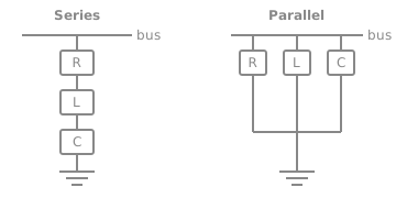
Three-phase passive RLC load shunted to ground (grounded-Y, one bus port; the return is an internal ground). Two data-entry modes (the data_entry selector): RLC = enter per-phase R, L and C each in their own unit (Ω / pu / Siemens for R; H / pu / reactance for L; F / pu / susceptance for C) with a topology selector (Series = one R + L + C branch from bus to ground; Parallel = R, L and C each independently bus → ground, R ∥ L ∥ C). PQ = enter the 3-phase total real power P, inductive reactive power Ql and capacitive reactive power Qc (MW·Mvar / kW·kvar / pu); the equivalent parallel R‖L‖C per phase is back-solved from the load-flow base voltage V_base (RMS line-to-line): R = V_base²/P, L = V_base²/(Ql·2πf), C = Qc/(2πf·V_base²). Any element can be omitted by entering 0 — in Series that shorts the element out, in Parallel (and in PQ mode) it opens it (removes it). Carries an EMT trapezoidal companion AND a load-flow FIXED SHUNT row derived from the equivalent per-phase admittance. Use for damping banks, harmonic filters, balanced static loads, and shunt reactor / capacitor banks.
Category: Three-Phase / Passive
The RLC Load is a balanced three-phase passive load wired between a single bus and an internal ground (a grounded-Y / star connection). You give it a resistance, an inductance and a capacitance — each in the unit that suits your data — and choose how the three elements combine per phase. It carries both a time-domain (EMT) model and a power-flow shunt, so the same component works in a transient run and in a load-flow study.
Data entry: RLC or PQ
The Data entry selector picks how you describe the load:
- RLC data — enter the per-phase resistance, inductance and capacitance directly, plus a topology (Series or Parallel). This is the mode described in the rest of this page.
- PQ data — enter the load by its power instead of its impedance: the 3-phase total real power
, the inductive reactive power and the capacitive reactive power . The component back-solves an equivalent parallel R‖L‖C per phase from the base voltage (RMS line-to-line, on the Units tab):
Enter
Topology
The Topology selector decides how R, L and C combine on each phase, between the bus and the internal ground:
- Series R-L-C — one branch per phase: the resistor, inductor and capacitor are in series. The per-phase impedance is
- Parallel R‖L‖C — the resistor, inductor and capacitor each hang independently from the bus to ground. The per-phase admittance is
Omitting an element
Set any value to 0 to leave that element out. Because "leaving it out" means different things in the two topologies, the value 0 is interpreted to match the physical intent:
| Element set to 0 | Series | Parallel |
|---|---|---|
| R = 0 | short (no resistance) | open (no resistor) |
| L = 0 | short (no inductor) | open (no inductor) |
| C = 0 | short (no capacitor) | open (no capacitor) |
So a Series load with C = 0 is a series R-L branch; a Parallel load with C = 0 is a parallel R‖L. The default (C = 0) is an R-L load.
Units
R, L and C each carry their own unit dropdown. You can enter:
- R — ohms (Ω), kΩ, per-unit, or siemens (S).
- L — henries (H), mH, per-unit, reactance X in ohms, or X in pu.
- C — farads (F), µF, per-unit, susceptance B in siemens, or B in pu.
Per-unit, reactance and susceptance choices read the system bases (base voltage, base power and frequency) from the Units tab. The value you type is converted to SI internally, so the simulation always sees a consistent R (Ω), L (H) and C (F) regardless of how you entered it.
Power-flow (load-flow) behaviour
In a load-flow study the load appears as a fixed shunt at its bus. The per-phase equivalent admittance (Y = G + jB) (computed from R, L, C and the topology above) sets the shunt's real and reactive draw:
with the sign convention that a positive (B_L) injects reactive power at the bus (capacitive) and a negative (B_L) absorbs it (inductive). The reference voltage is the base voltage on the Units tab — set it to the voltage of the bus the load sits on so the power-flow draw matches the operating point.
Current monitoring
Turn on Measure current to publish the per-phase load current (positive = drawn from the bus into the load) as observable signals. Name each phase on the Measure current row; leave a name blank to skip that phase.
Typical uses
- A balanced static load (R-L) on a feeder.
- A shunt capacitor bank (Parallel, C only) for power-factor correction, or a shunt reactor (Parallel, L only).
- A damping resistor or a simple harmonic filter branch (Series R-L-C tuned to a notch frequency).
Ports
| Port | Kind | Signal | Notes |
|---|---|---|---|
bus | Three-phase terminal | — |
Parameters
Config
| Parameter | Type | Default | Units | Description | ID |
|---|---|---|---|---|---|
| Data entry | Choice: RLC data / PQ data | RLC data | — | How the load is specified. RLC: enter per-phase R, L and C directly, with a topology selector (Series or Parallel) — fields are on the RLC Data tab. PQ: enter the 3-phase total real power P, inductive reactive power Ql and capacitive reactive power Qc — fields are on the PQ Data tab. PQ is always an equivalent parallel R‖L‖C per phase, back-solved from the load-flow base voltage V_base (RMS line-to-line, Units tab): R = V_base²/P, L = V_base²/(Ql·2πf), C = Qc/(2πf·V_base²). | data_entry |
| Measure current | Choice: Off / On | Off | — | Emit per-phase load current (positive = drawn from the bus into the load) as simulator observables. Signal names are on this row; blank skips a phase. | measure_current |
| Positive direction | Choice: +ve in / +ve out | +ve in | — | Sign convention for this current. '+ve in' (default) is positive when current flows into the load from the bus, on every phase. '+ve out' flips the sign. | current_dir |
RLC Data
| Parameter | Type | Default | Units | Description | ID |
|---|---|---|---|---|---|
| Topology | Choice: Series R-L-C / Parallel R‖L‖C | Parallel R‖L‖C | — | How the three per-phase elements combine between the bus and the internal ground. Series: one R + L + C branch (Z = R + j(ωL − 1/ωC)). Parallel: R, L and C each independently bus → ground (Y = 1/R + 1/(jωL) + jωC). Omitting an element (value 0) shorts it in Series and opens it in Parallel. | topology |
| R | Number | 100 | Ω (also kΩ, pu, S) | Per-phase resistance. Pick a unit from the dropdown; pu / Siemens conversions read the bases from the Units tab. Enter 0 to omit the resistor (Series: short; Parallel: open). | resistance |
| L | Number | 0.1 | H (also mH, pu, Ω, X.pu) | Per-phase inductance. Pick a unit from the dropdown; pu / X (Ω reactance) / X.pu conversions read the bases from the Units tab. Enter 0 to omit the inductor (Series: short; Parallel: open). | inductance |
| C | Number | 0 | F (also μF, pu, S, B.pu) | Per-phase capacitance. Pick a unit from the dropdown; pu / B (Siemens susceptance) / B.pu conversions read the bases from the Units tab. Enter 0 to omit the capacitor (Series: short; Parallel: open). Default 0 = no capacitor (RL load). | capacitance |
PQ Data
| Parameter | Type | Default | Units | Description | ID |
|---|---|---|---|---|---|
| P | Number | 100 | MW (also kW, pu) | Three-phase total real power drawn by the load at V_base. Sets the equivalent per-phase resistance R = V_base² / P (parallel R‖L‖C). Enter 0 to omit the resistor. | pr |
| Ql | Number | 0 | Mvar (also kvar, pu) | Three-phase total reactive power absorbed by the inductive part at V_base (positive = inductive / lagging). Sets the equivalent per-phase inductance L = V_base² / (Ql · 2πf) (parallel R‖L‖C). Enter 0 to omit the inductor. | ql |
| Qc | Number | 0 | Mvar (also kvar, pu) | Three-phase total reactive power generated by the capacitive part at V_base (positive = capacitive / leading). Sets the equivalent per-phase capacitance C = Qc / (2πf · V_base²) (parallel R‖L‖C). Enter 0 to omit the capacitor. | qc |
Current Monitoring
| Parameter | Type | Default | Units | Description | ID |
|---|---|---|---|---|---|
| Phase A current name | Text | Ia | — | Signal name for the Phase A load current. Blank skips this phase. | current_name_a |
| Phase B current name | Text | Ib | — | Signal name for the Phase B load current. Blank skips this phase. | current_name_b |
| Phase C current name | Text | Ic | — | Signal name for the Phase C load current. Blank skips this phase. | current_name_c |
Units
| Parameter | Type | Default | Units | Description | ID |
|---|---|---|---|---|---|
| S_base (MVA) | Number | 100 | — | System base apparent power in MVA. Used by `pu` impedance / admittance conversions in this component's `computations` block. | S_base |
| V_base (kV) | Number | 230 | — | Base RMS line-to-line voltage in kV. Used by `pu` impedance / admittance conversions in this component's `computations` block. | V_base |
| Frequency (Hz) | Number | 60 | — | Frequency in Hz. Used by `B` (susceptance) / `X` (reactance) conversions in this component's `computations` block. | Freq |
Observables
| Default name | Kind | Recorded when | Description | ID |
|---|---|---|---|---|
| set by Phase A current name | Signal | Measure current is on | Phase A load current (A). Positive = current drawn from the bus into the load. The direction switch keeps this sign by default and flips it the other way. | branchCurrent_a |
| set by Phase B current name | Signal | Measure current is on | Phase B load current (A). Positive into the load from the bus, on every phase for '+ve in' (default); the other direction flips the sign. | branchCurrent_b |
| set by Phase C current name | Signal | Measure current is on | Phase C load current (A). Positive into the load from the bus, on every phase for '+ve in' (default); the other direction flips the sign. | branchCurrent_c |