

Appearance
Synchronous Machine (3-phase)
Three-phase synchronous machine (generator/motor) modeled in the dq0 / Park reference frame following Kundur's complete two-axis model (Power System Stability and Control, §3.4). The rotor carries a field winding plus damper windings — one d-axis damper and, for a round-rotor machine, two q-axis dampers (field + 1d + 1q + 2q); a salient-pole machine drops the second q-axis damper (field + 1d + 1q). The seven flux linkages are integrated with full stator transients (the pψd / pψq speed-and-transformer EMFs are retained), so the model is accurate for switching and fault transients, not just slow swings. Parameters are entered as the usual datasheet quantities (Xd, Xq, X'd, X'q, X''d, X''q, leakage Xl, Ra, and the open-circuit time constants T'do, T''do, T'qo, T''qo) and converted internally to Kundur's fundamental circuit parameters (Lad, Lfd, L1d, Rfd, R1d, Laq, L1q, L2q, R1q, R2q). Alternatively, the Parameter-entry mode can be switched to Fundamental to type those equivalent-circuit parameters directly (the form many textbooks tabulate), skipping the datasheet conversion. Magnetic saturation is the exponential open-circuit saturation curve acting on the d-axis magnetizing inductance (q-axis scaled by the same factor), specified either directly by its exponential coefficients (Asat, Bsat) or by the two datasheet saturation factors SE(1.0) and SE(1.2) (the GENROU/GENSAL convention SE = ΔI/Vt), which are fit to the same curve. The machine couples to the network by the EMTDC-style voltage-behind-subtransient-reactance method as a mutually-coupled three-phase stator companion: the positive/negative sequence sees Z1 = Ra + jX''avg while the zero sequence sees the machine's own Z0 = R0 + jX0 (entered in pu), plus a per-step Norton current source carrying the internal sub-transient EMF (from the rotor fluxes) and the trapezoidal history. The star point is internal (no exposed neutral terminal): the grounding mode selects ungrounded (no zero-sequence path), solidly grounded, or grounded through an impedance Rn+jXn, so the terminal zero-sequence impedance is the standard Z0 + 3·(Rn+jXn) and unbalanced faults / zero-sequence studies behave correctly. Field voltage Efd and mechanical torque Tm are wired control inputs (with constant fallbacks when unwired); rotor speed ω, field current Ifd, terminal-voltage magnitude Vt (pu, positive-sequence) and electrical power Pe and reactive power Qe (pu on the machine base, filtered) are wired control outputs — feed Vt and Ifd to an excitation system / AVR (e.g. the Type DC1A exciter), Ifd to an over-excitation limiter, Vt / Pe / Qe to an under-excitation limiter, and feed ω and Pe to a turbine-governor (e.g. the GGOV1 governor, which drives Tm back). The left-edge ω / Pe / Tm ports line up with the governor's right-edge ports for a direct connection. An optional rotor lock can start the run with the shaft mechanically held (swing/torsional dynamics frozen, speed held at ω(0)) while the network settles, then release it either at a user-entered time or live under a named gate signal (0 = locked, 1 = free). Rotor angle, real power P, reactive power Q, electrical torque Te, and the three stator currents are optional observables, each with its own unit selector and name. Reactances are entered in pu on the machine's own MVA / kV base (or in Ω). The Name parameter is a display-only label drawn under the icon with the rated power. Standalone machine — wire an external step-up transformer, breaker, or loads on the canvas.
Category: Three-Phase / Machines
Overview
The Synchronous Machine models a three-phase synchronous generator (or motor) — the workhorse of bulk power generation. The stator carries the three armature windings; the rotor carries a DC field winding (fed by the excitation system) plus short-circuited damper windings that account for sub-transient behaviour. The model follows Kundur, Power System Stability and Control, §3 (the complete two-axis / dq0 model with stator transients retained).
Salient-pole vs. round rotor
Two rotor constructions are supported through the Rotor type parameter; they differ in how the air gap — and therefore the magnetic reluctance — varies with rotor position.
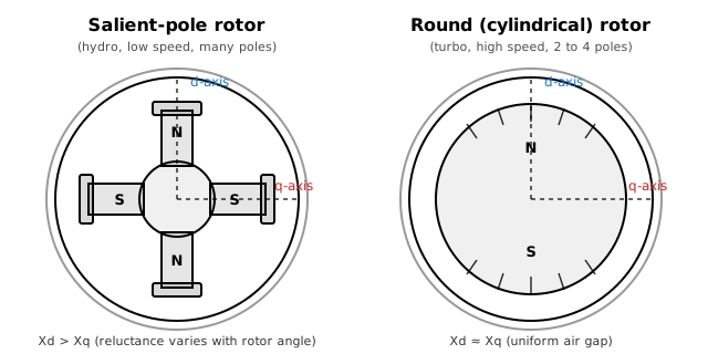
- Salient-pole (hydro units, low speed, many poles): the poles physically project, so the air gap is small on the direct (d) axis and large on the quadrature (q) axis. This gives
and an extra reluctance torque. Salient-pole machines have one q-axis damper winding (field + 1d + 1q). - Round / cylindrical (turbo-generators, 2–4 poles, high speed): a uniform air gap gives
. The solid steel rotor supports eddy currents modelled as a second q-axis damper (field + 1d + 1q + 2q).
The dq0 (Park) reference frame
The three stator phase quantities are transformed to a rotor-fixed reference frame by Park's transformation, giving direct (
The stator and rotor voltage equations in per-unit, with full stator transients retained, are (Kundur eqs. 3.120–3.123):
where
Equivalent circuits
Because the dq0 inductances are constant, each axis reduces to a coupled magnetic circuit sharing a common mutual (magnetizing) inductance
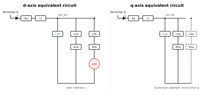
The flux linkages (per unit) are
with
Datasheet vs. fundamental parameter entry
Many references (and Kundur's §5 worked examples) tabulate a machine directly by its fundamental equivalent-circuit parameters rather than the operational reactances and time constants. The Parameter entry setting on the Config tab chooses which form you type:
- Datasheet (default) — enter
, the leakage , and the four open-circuit time constants. The fundamental parameters are derived from them. - Fundamental — enter
directly ( only for a round rotor). No conversion step is applied.
Both forms feed the identical machine model — only the input representation differs.
Torque and rotor dynamics
The air-gap electromagnetic torque is
The rotor accelerates per the swing equation (per unit, inertia constant
where
This single inertia is the right choice for electromechanical (swing-stability) studies. For torsional / sub-synchronous studies, switch the Shaft model to Multi-mass, which replaces this one lumped rotor with the spring-coupled mass chain described next (the single-mass model is just its one-mass special case).
Multi-mass shaft (torsional model)
Real turbine-generators are not a single rigid rotor: the HP / IP / LP turbine stages, the generator and the exciter sit on one long shaft and are coupled through finite torsional stiffness. The shaft therefore twists and oscillates, with natural frequencies typically in the 10-50 Hz range. These torsional modes can be excited by network events and, most importantly, by series-compensated lines, leading to sub-synchronous resonance (SSR) that can fatigue or break a shaft. Capturing them needs more than one inertia.
Selecting Multi-mass on the Shaft tab models the shaft as a role-based chain built around the generator: 1 to 4 turbine masses, the generator rotor, and an optional exciter mass (up to six masses in all):
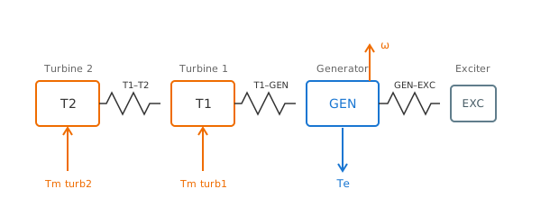
Each mass carries its own inertia constant
The generator mass is the electrical rotor: it is the only one that exchanges the air-gap electrical torque
For an undamped two-mass shaft (one turbine + the generator) the twist rings at the torsional natural frequency
and the mutual damping
Per-stage mechanical torque
In multi-mass mode the single
On the canvas the icon grows to match: the electrical machine body stays on the right (keeping the three-phase terminal clear), with the generator drum at a fixed position to its left, the exciter drum (when modeled) filling the slot between them, and the turbine drums fanning out further left — each turbine with its torque pin on top and the speed output rising from the generator drum. With no exciter the gen-to-body section is simply drawn as slack shaft.
The shaft starts untwisted and synchronized; enabling Measure shaft (per-mass) publishes each mass's speed and angle as role-named observables (Generator, Turbine 1…4, Exciter), so the torsional oscillations — and the twist between any two masses — can be plotted directly.
Rotor lock (locked-rotor start)
It is often useful to hold the rotor mechanically still while the electrical network energizes and the fast transients die away, and only then let the rotor swing. The Rotor lock setting (Excitation & Mechanical tab) does exactly that.
While the rotor is locked, its mechanical dynamics are frozen: the swing equation (and, in multi-mass mode, every per-mass swing and shaft twist) is not integrated, so the speed is held at its initial value
With the usual
pu (synchronous), a locked rotor turns at exactly synchronous speed with a constant load angle — i.e. it behaves as a fixed-angle source until released. This makes it a convenient way to bring a network up to a clean operating point before arming the swing dynamics.
Three modes are offered:
| Mode | Behaviour |
|---|---|
| Off | The rotor is free from |
| Timed unlock | The rotor stays locked until the Unlock time, then runs free for the rest of the simulation. |
| Signal-controlled | A named gate signal sets the lock live: the rotor is locked while the signal is 0 (below 0.5) and free while it is 1 (at/above 0.5), and it re-locks if the signal returns to 0. |
In Signal-controlled mode, type the name of any published signal into Lock signal name — a GoTo output, a labelled wire, or any component's observable. The gate is read one step delayed (so it can never form an algebraic loop), and a blank or unresolved name reads 0, keeping the rotor locked. This lets a switch, a comparator, or a timer elsewhere on the canvas drive the release — for example, unlocking the rotor only after a breaker closes or a bus voltage crosses a threshold.
The lock applies identically to the single-mass and the multi-mass shaft models; in multi-mass mode the whole shaft (all masses and all twists) is held and then released together.
Soft-start ramp
When the machine is initialized onto a load-flow operating point, its rotor flux (and hence field) starts on that point, but the stator energizes from rest — so by default the armature takes a brief "switch closes at
The Soft-start τ setting (Excitation & Mechanical tab) removes it. With
Soft-start and Rotor lock compose well: lock the rotor, ramp the electrical side in cleanly, then release the swing dynamics once the network is settled.
Magnetic saturation
Saturation derates the magnetizing inductance as a function of the air-gap (mutual) flux
with the q-axis magnetizing inductance scaled by the same factor. The curve can be entered two equivalent ways (selected by the Definition field on the Saturation tab):
- Exponential — give
and directly. - SE points — give the two datasheet saturation factors
and . These are the GENROU/GENSAL convention : the fractional extra field current (vs. the air-gap line) needed to reach terminal voltage on the open-circuit curve. The exponential is fit through the two points:
The same saturation convention is shared across the machine models (and, in future, transformers), so an SE-point curve entered here behaves identically wherever saturation is offered.
Network interface and grounding
The machine couples to the electrical network by the EMTDC-style voltage-behind-sub-transient-reactance method, realised as a mutually-coupled three-phase stator companion. Decomposed into symmetric sequences:
- the positive / negative sequence sees the sub-transient interface impedance
, with ; - the zero sequence sees the machine's own impedance
(entered in pu on the Zero Sequence tab). Because the companion is genuinely coupled (not three independent per-phase branches), may legitimately be smaller than — the usual case for a real machine.
A per-step Norton current source carries the internal sub-transient EMF (reconstructed from the rotor fluxes) plus the trapezoidal history.
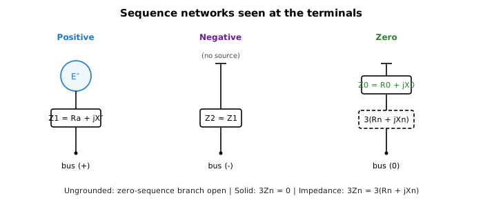
There is no exposed neutral terminal. The star (neutral) point is internal, and the Neutral grounding mode selects how it ties to ground:
| Mode | Terminal zero-sequence impedance |
|---|---|
| Ungrounded | open — no zero-sequence current path |
| Solidly grounded (default) | |
| Grounded via impedance |
The factor of 3 is the standard symmetric-component result for a neutral impedance carrying
Display label
The Name parameter (Config tab) is a display-only tag (e.g. MP-3). It is drawn beneath the icon, on the line above the machine's rated power, and has no effect on the simulation.
When to use something else
- Stiff/ideal source behind a fixed impedance (no rotor dynamics needed): use the 3-Phase Voltage Source, which is far cheaper.
- A machine on a different MVA/kV base wired to the grid: add an external step-up Transformer (3-phase) rather than re-basing the machine by hand.
Ports
| Port | Kind | Signal | Notes |
|---|---|---|---|
terminals | Three-phase terminal | — | |
Efd | Control input | Real | |
Tm | Control input | Real | Shown when Shaft model is Single-mass (lumped) |
Tm_turb1 | Control input | Real | Shown when Shaft model is Multi-mass (torsional) and Number of turbines is at least 1 |
Tm_turb2 | Control input | Real | Shown when Shaft model is Multi-mass (torsional) and Number of turbines is at least 2 |
Tm_turb3 | Control input | Real | Shown when Shaft model is Multi-mass (torsional) and Number of turbines is at least 3 |
Tm_turb4 | Control input | Real | Shown when Shaft model is Multi-mass (torsional) and Number of turbines is at least 4 |
speed | Control output | Real | |
Ifd | Control output | Real | |
Vt | Control output | Real | |
Pe | Control output | Real | |
Qe | Control output | Real |
Parameters
Config
| Parameter | Type | Default | Units | Description | ID |
|---|---|---|---|---|---|
| Name | Text | (empty) | — | Display-only label for this machine (e.g. a tag like `MP-3`). Drawn under the icon above the rated power. Has no effect on the simulation. | name |
| Rotor type | Choice: Round-rotor (field + 1d + 1q + 2q) / Salient-pole (field + 1d + 1q) | Round-rotor (field + 1d + 1q + 2q) | — | Rotor winding structure. `Round-rotor` (turbo-generator) carries a field winding, one d-axis damper and two q-axis dampers (field + 1d + 1q + 2q) and uses X'q and T'qo. `Salient-pole` (hydro) drops the second q-axis damper (field + 1d + 1q); X'q and T'qo are not used. | rotor_type |
| Parameter entry | Choice: Datasheet (Xd, X'd, T'do, ...) / Fundamental (Lad, Lfd, Rfd, ...) | Datasheet (Xd, X'd, T'do, ...) | — | How the electrical machine parameters are entered. `Datasheet` takes the usual operational quantities (Xd, Xq, X'd, X'q, X''d, X''q, leakage Xl, Ra and the open-circuit time constants) and converts them internally to Kundur's fundamental circuit parameters. `Fundamental` skips that conversion and lets you type the equivalent-circuit parameters directly (Lad, Laq, Ll, Lfd, L1d, L1q, L2q, Ra, Rfd, R1d, R1q, R2q) — the form many textbooks (e.g. Kundur §5) tabulate. The two modes select different parameter tabs; everything downstream (companion model, saturation, dynamics) is identical. | param_input_mode |
| Shaft model | Choice: Single-mass (lumped) / Multi-mass (torsional) | Single-mass (lumped) | — | Mechanical rotor representation. `Single-mass` lumps the whole turbine-generator into one inertia governed by the scalar swing equation 2H·dω/dt = Tm − Te − D·(ω−1) — the right choice for electromechanical (swing-stability) studies. `Multi-mass` replaces it with a chain of spring-coupled rotor masses (HP / IP / LP turbine stages, generator, exciter) for torsional / sub-synchronous-resonance (SSR) studies; configure the masses, shaft stiffnesses and per-stage mechanical-torque inputs on the Shaft tab. | shaft_model |
| S rated | Number | 100 | MVA (also VA, kVA) | Machine rated apparent power. Also the per-unit power base for the reactances/resistances and the basis for the pu electrical torque Te. | s_rated |
| V rated (LL rms) | Number | 13.8 | kV (also V) | Machine rated line-to-line RMS terminal voltage. Per-unit voltage base; the internal EMF for a 1 pu field is V_rated·√(2/3) peak line-to-neutral. | v_rated |
| f rated | Number | 60 | — | Rated electrical frequency (Hz). Sets the base angular speed ω0 = 2πf and the pu↔SI reactance/inductance conversion. | f_rated |
| H (MWs/MVA) | Number | 3.5 | — | Inertia constant in seconds (stored kinetic energy at rated speed / rated MVA). Larger H = slower speed deviations. Used by the single-mass swing equation 2H·dω/dt = Tm − Te − D·(ω−1). Single-mass shaft only — in multi-mass mode each rotor mass carries its own H on the Shaft tab. | H |
| D (pu) | Number | 0 | — | Per-unit mechanical damping torque coefficient (damping torque = D·(ω−1) in pu). 0 disables. Single-mass shaft only — in multi-mass mode each rotor mass carries its own self-damping on the Shaft tab. | D |
| Neutral grounding | Choice: Ungrounded / Solidly grounded / Grounded via impedance | Solidly grounded | — | How the machine's internal star point is tied to ground (there is no exposed neutral terminal). `Ungrounded`: the star point floats — no zero-sequence current path. `Solid`: star point bonded to ground (terminal zero-sequence impedance = the machine Z0 = R0 + jX0). `Impedance`: star point grounded through Rn + jXn (a neutral grounding resistor/reactor), so the terminal zero-sequence impedance is Z0 + 3·(Rn + jXn). Set the machine Z0 on the Zero Sequence tab. | grounding_mode |
| Magnetic saturation | Choice: Off (linear) / On | Off (linear) | — | Enable the exponential open-circuit saturation curve (Kundur §3.8) acting on the d-axis magnetizing inductance Lad, with the q-axis scaled by the same factor. Define the curve directly (Asat/Bsat) or via the SE(1.0)/SE(1.2) datasheet points on the Saturation tab. | saturation |
| Measure stator current | Choice: Off / On | Off | — | Emit the three stator phase currents as observables. Signal names and units are on this row. | measure_current |
| Positive direction | Choice: +ve in / +ve out | +ve out | — | Sign convention for this current. '+ve out' (default) is positive when current flows out of the stator terminals into the network. '+ve in' flips the sign. | current_dir |
| Measure rotor angle | Choice: Off / On | Off | — | Emit the rotor (load) angle δ as an observable, wrapped to [-180°, 180°). The signal name and unit are on this row. | measure_angle |
| Measure elec. torque | Choice: Off / On | Off | — | Emit the air-gap electrical torque Te as an observable. The signal name and unit are on this row. | measure_te |
| Measure shaft (per-mass) | Choice: Off / On | Off | — | Emit each rotor mass's speed and angle as observables (multi-mass shaft only). Use the per-mass speeds and the angle twists between adjacent masses to study torsional / sub-synchronous oscillations. Signal names are on this row. | measure_shaft |
| Monitor P/Q | Choice: Off / On | Off | — | Emit real (P) and reactive (Q) power delivered at the terminals as observables. Instantaneous Buchholz/Akagi form, low-pass filtered with pq_time_constant to reject 2ω ripple. Signal names and units are on this row. | monitor_pq |
| P/Q filter τ (sec) | Number | 0.02 | — | Low-pass filter time constant for P/Q (and the Te report). Smaller tracks transients; larger gives a cleaner steady state. | pq_time_constant |
Reactances
| Parameter | Type | Default | Units | Description | ID |
|---|---|---|---|---|---|
| Xd | Number | 1.8 | pu (also Ω) | Direct-axis synchronous reactance. Enter in pu on the machine base or in Ω. | Xd |
| Xq | Number | 1.7 | pu (also Ω) | Quadrature-axis synchronous reactance. Enter in pu on the machine base or in Ω. | Xq |
| X'd | Number | 0.3 | pu (also Ω) | Direct-axis transient reactance. Enter in pu on the machine base or in Ω. | Xdp |
| X'q | Number | 0.55 | pu (also Ω) | Quadrature-axis transient reactance. Round-rotor machines only (a salient-pole rotor has a single q-axis damper and no transient q-axis branch). Enter in pu on the machine base or in Ω. | Xqp |
| X''d | Number | 0.2 | pu (also Ω) | Direct-axis sub-transient reactance. Sets (averaged with X''q) the constant companion conductance that interfaces the machine to the network. Enter in pu on the machine base or in Ω. | Xdpp |
| X''q | Number | 0.2 | pu (also Ω) | Quadrature-axis sub-transient reactance. Saliency (X''d ≠ X''q) is carried in the per-step injection; the average sets the constant companion conductance. Enter in pu on the machine base or in Ω. | Xqpp |
| Xl (leakage) | Number | 0.13 | pu (also Ω) | Stator (armature) leakage reactance. With Xd / Xq it fixes the magnetizing inductances Lad = Xd − Xl and Laq = Xq − Xl in Kundur's fundamental model. Enter in pu on the machine base or in Ω. | Xl |
| Ra | Number | 0.002 | pu (also Ω) | Stator (armature) resistance per phase. Enter in pu on the machine base or in Ω. | Ra |
Time Constants
| Parameter | Type | Default | Units | Description | ID |
|---|---|---|---|---|---|
| T'do | Number | 8 | s (also ms) | Direct-axis transient open-circuit time constant. | Tdop |
| T''do | Number | 0.03 | s (also ms) | Direct-axis sub-transient open-circuit time constant. | Tdopp |
| T'qo | Number | 0.4 | s (also ms) | Quadrature-axis transient open-circuit time constant. Round-rotor machines only. | Tqop |
| T''qo | Number | 0.05 | s (also ms) | Quadrature-axis sub-transient open-circuit time constant. | Tqopp |
Fundamental Params
| Parameter | Type | Default | Units | Description | ID |
|---|---|---|---|---|---|
| Lad | Number | 1.66 | pu (also Ω) | Direct-axis mutual (magnetizing) inductance — the unsaturated air-gap inductance shared by the stator and the d-axis rotor windings. With the leakage gives Xd = Lad + Ll. Enter in pu on the machine base or as a reactance in Ω. | Lad |
| Laq | Number | 1.61 | pu (also Ω) | Quadrature-axis mutual (magnetizing) inductance, shared by the stator and the q-axis rotor windings. With the leakage gives Xq = Laq + Ll. Enter in pu on the machine base or as a reactance in Ω. | Laq |
| Ll (leakage) | Number | 0.15 | pu (also Ω) | Stator (armature) leakage inductance. Synchronous inductances are Ld = Ll + Lad and Lq = Ll + Laq. Enter in pu on the machine base or as a reactance in Ω. | Ll |
| Ra | Number | 0.003 | pu (also Ω) | Stator (armature) resistance per phase. Enter in pu on the machine base or in Ω. | Ra_fund |
| Lfd (field leakage) | Number | 0.165 | pu (also Ω) | Field-winding leakage inductance (d-axis rotor), referred to the stator. With Lad sets the d-axis transient inductance L'd = Ll + Lad‖Lfd. Enter in pu on the machine base or as a reactance in Ω. | Lfd |
| Rfd (field) | Number | 0.0006 | pu (also Ω) | Field-winding resistance (d-axis rotor), referred to the stator. Sets the d-axis transient open-circuit time constant T'do = (Lad + Lfd)/(ω0·Rfd). Enter in pu on the machine base or in Ω. | Rfd |
| L1d (damper leakage) | Number | 0.1713 | pu (also Ω) | d-axis damper-winding leakage inductance, referred to the stator. With Lad and Lfd sets the d-axis sub-transient inductance L''d = Ll + Lad‖Lfd‖L1d. Enter in pu on the machine base or as a reactance in Ω. | L1d |
| R1d (damper) | Number | 0.0284 | pu (also Ω) | d-axis damper-winding resistance, referred to the stator. Sets the d-axis sub-transient open-circuit time constant T''do = (L1d + Lad‖Lfd)/(ω0·R1d). Enter in pu on the machine base or in Ω. | R1d |
| L1q (damper leakage) | Number | 0.7252 | pu (also Ω) | First q-axis damper-winding leakage inductance, referred to the stator. On a salient-pole machine this is the only q-axis damper. Enter in pu on the machine base or as a reactance in Ω. | L1q |
| R1q (damper) | Number | 0.00619 | pu (also Ω) | First q-axis damper-winding resistance, referred to the stator. Enter in pu on the machine base or in Ω. | R1q |
| L2q (2nd damper leakage) | Number | 0.125 | pu (also Ω) | Second q-axis damper-winding leakage inductance (round-rotor only — models the solid-rotor eddy-current path). Enter in pu on the machine base or as a reactance in Ω. | L2q |
| R2q (2nd damper) | Number | 0.02368 | pu (also Ω) | Second q-axis damper-winding resistance (round-rotor only), referred to the stator. Enter in pu on the machine base or in Ω. | R2q |
Saturation
| Parameter | Type | Default | Units | Description | ID |
|---|---|---|---|---|---|
| Definition | Choice: Exponential (Asat/Bsat) / SE points (SE1.0/SE1.2) | Exponential (Asat/Bsat) | — | How the saturation curve is specified. `Exponential` enters the coefficients Asat / Bsat directly. `SE points` enters the two datasheet saturation factors SE(1.0) and SE(1.2); the exponential is fit through them. Both end up as the same Ssat(ψ) = Asat·exp(Bsat·(ψ − ψT1)) curve internally. | sat_definition |
| Asat | Number | 0.03 | — | Exponential saturation coefficient A (Kundur eq. 3.187): the saturation function is Ssat(ψat) = Asat·exp(Bsat·(ψat − ψT1)) for air-gap flux ψat above the threshold ψT1, else 0. The saturated magnetizing inductance is Lad = Ladu / (1 + Ssat). 0 disables saturation. | Asat |
| Bsat | Number | 7 | — | Exponential saturation coefficient B (1/pu-flux): controls how sharply saturation increases with air-gap flux above ψT1. | Bsat |
| SE(1.0) | Number | 0.1 | — | Open-circuit saturation factor at Vt = 1.0 pu: SE(1.0) = ΔI(1.0)/1.0, the fractional extra field current (vs. the air-gap line) needed to reach 1.0 pu terminal voltage. Typical 0.05–0.15. | SE10 |
| SE(1.2) | Number | 0.3 | — | Open-circuit saturation factor at Vt = 1.2 pu: SE(1.2) = ΔI(1.2)/1.2. Must exceed SE(1.0). Typical 0.2–0.5. With SE(1.0) it fixes Bsat = ln(SE12/SE10)/0.2 and Asat = SE10/exp(Bsat·(1.0 − ψT1)). | SE12 |
| ψT1 (pu) | Number | 0.8 | — | Air-gap flux threshold (pu) below which the iron is unsaturated (Ssat = 0). | psiT1 |
Zero Sequence
| Parameter | Type | Default | Units | Description | ID |
|---|---|---|---|---|---|
| X0 | Number | 0.1 | pu (also Ω) | Machine zero-sequence reactance. Sets the zero-sequence stator impedance Z0 = R0 + jX0 (carried by a true mutually-coupled stator companion, so X0 may be smaller than the sub-transient X''). Leave at/near 0 to default to the average sub-transient reactance X''avg. Enter in pu on the machine base or in Ω. | X0 |
| R0 | Number | 0 | pu (also Ω) | Machine zero-sequence resistance. Defaults to the armature resistance Ra when left at 0. Enter in pu on the machine base or in Ω. | R0 |
Grounding
| Parameter | Type | Default | Units | Description | ID |
|---|---|---|---|---|---|
| Rn (neutral) | Number | 0 | pu (also Ω) | Neutral grounding resistance, between the internal star point and ground. Adds 3·Rn to the terminal zero-sequence impedance. Enter in pu on the machine base or in Ω. | Rn |
| Xn (neutral) | Number | 0 | pu (also Ω) | Neutral grounding reactance, between the internal star point and ground. Adds 3·Xn to the terminal zero-sequence impedance. Enter in pu on the machine base or in Ω. | Xn |
Excitation & Mechanical
| Parameter | Type | Default | Units | Description | ID |
|---|---|---|---|---|---|
| Efd (fallback, pu) | Number | 1 | — | Constant per-unit field voltage used when the Efd control input is left unwired. 1.0 ≈ rated open-circuit terminal voltage at no load (unsaturated). | efd0 |
| Tm (fallback, pu) | Number | 0 | — | Constant per-unit mechanical torque used when the Tm control input is left unwired. Positive drives the machine as a generator. | tm0 |
| ω(0) (pu) | Number | 1 | — | Initial rotor speed in pu of synchronous speed. 1.0 starts synchronized. | init_speed |
| δ(0) | Number | 0 | deg (also rad) | Initial rotor (load) angle δ(0) = arg(Eq) relative to the synchronous reference at t=0 — the q-axis EMF angle that every stability text reports. Overwritten by an applied load-flow result when the machine participates in power flow. (Internally the engine seeds the Park rotor state 180° from δ — the network is sine-referenced — and the reported angle adds the offset back, so you set and read the textbook δ.) | init_angle |
| id(0) (pu) | Number | 0 | — | Initial d-axis stator current (pu, generator convention) used to seed the loaded steady-state rotor flux so the machine relaxes onto its operating point (a short armature transient rings down; the stator current is not pre-charged). Managed by the load-flow apply pass; leave at 0 for the open-circuit / standalone start. | id0 |
| iq(0) (pu) | Number | 0 | — | Initial q-axis stator current (pu, generator convention) used to seed the loaded steady-state rotor flux so the machine relaxes onto its operating point (a short armature transient rings down; the stator current is not pre-charged). Managed by the load-flow apply pass; leave at 0 for the open-circuit / standalone start. | iq0 |
| Rotor lock | Choice: Off (free from t=0) / Timed unlock / Signal-controlled | Off (free from t=0) | — | Start the run with the rotor mechanically locked and release it later, so the electrical transients can settle before the rotor is allowed to swing. While locked, the rotor's mechanical dynamics are frozen: speed is held at ω(0) and the load angle δ (and, in multi-mass mode, every shaft twist) is held constant. The electrical model keeps running normally throughout — the EMF still rotates at the held speed, currents and fluxes evolve — only the mechanical acceleration is suppressed. `Off`: rotor is free from t=0 (default behaviour). `Timed unlock`: rotor stays locked until the Unlock time, then runs free for the rest of the simulation. `Signal-controlled`: a named signal gates the lock live — the rotor is locked while the signal is 0 (below 0.5) and free while it is 1 (at/above 0.5), and it re-locks if the signal returns to 0. Applies to both the single-mass and the multi-mass shaft model. | rotor_lock |
| Unlock time | Number | 1 | s (also ms) | Simulation time at which the locked rotor is released into free dynamics. The rotor is locked for t < unlock time and free for t ≥ unlock time. | unlock_time |
| Lock signal name | Text | (empty) | — | Name of a published signal that gates the rotor lock: the rotor is locked while the signal is below 0.5 (0 = locked) and free at/above 0.5 (1 = free), re-locking live if the signal returns to 0. Resolved by name the same way as a GoTo output, a labelled wire, or another component's observable, and read 1-step delayed. Leave blank to keep the rotor locked for the whole run. | unlock_signal_name |
| Soft-start τ | Number | 0 | s (also ms) | Optional soft-start time constant. The rotor flux seed places the machine on its operating point, but the stator energises from rest, so by default the armature takes a brief 'switch closes at t=0' inrush that rings down over the armature time constant. Set a positive value to ramp the internal EMF (and stator current) in smoothly with this first-order time constant — the network energises with no inrush and is exactly on the operating point once the ramp completes (a few τ). While ramping, the field is held at its fallback so a wired AVR cannot wind up against the low ramp-time terminal voltage. A few cycles (≈ 0.03–0.1 s at 60 Hz) is typically enough. Leave at 0 to disable (legacy gentle start). | startup_tau |
Signal Names
| Parameter | Type | Default | Units | Description | ID |
|---|---|---|---|---|---|
| Phase A current name | Text | Ia | A (also kA) | Signal name for the Phase A stator current. Blank = skip. Value scaled to the chosen unit. | current_name_a |
| Phase B current name | Text | Ib | A (also kA) | Signal name for the Phase B stator current. Blank = skip. Value scaled to the chosen unit. | current_name_b |
| Phase C current name | Text | Ic | A (also kA) | Signal name for the Phase C stator current. Blank = skip. Value scaled to the chosen unit. | current_name_c |
| Rotor angle name | Text | delta | deg (also rad) | Signal name for the rotor (load) angle δ. Blank = skip. Wrapped to [-180°, 180°) and scaled to the chosen unit. | angle_name |
| Elec. torque name | Text | Te | pu (also N·m) | Signal name for the air-gap electrical torque Te. Blank = skip. Value scaled to the chosen unit. | te_name |
| P signal name | Text | P | MW (also W, kW) | Signal name for filtered real-power output P. Blank = skip. Value scaled to the chosen unit. | p_signal_name |
| Q signal name | Text | Q | MVAr (also VAr, kVAr) | Signal name for filtered reactive-power output Q. Blank = skip. Value scaled to the chosen unit. | q_signal_name |
Shaft
| Parameter | Type | Default | Units | Description | ID |
|---|---|---|---|---|---|
| Number of turbines | Choice: 1 / 2 / 3 / 4 | 1 | — | How many turbine masses drive the shaft (1 to 4). Each turbine is a spring-coupled rotor mass with its own mechanical-torque input pin; Turbine 1 sits next to the generator and higher-numbered turbines extend outward. With the generator (and optional exciter) this gives a 2- to 6-mass torsional chain — a large turbo-set is HP, IP, LP-A, LP-B (4 turbines), generator, exciter. | num_turbines |
| Model exciter mass | Choice: Off / On | Off | — | Add a separate exciter rotor mass on the far side of the generator from the turbines, coupled to the generator by its own shaft section. The exciter is an undriven inertia — it has no torque-input pin; its small steady mechanical torque is set by its fallback below. Off lumps the exciter into the generator mass. | model_exciter |
| Generator: H (MWs/MVA) | Number | 3.5 | — | Inertia constant of the generator rotor mass — the electrical rotor that exchanges the air-gap torque Te with the network and whose speed/angle drive the dq frame. | H_gen |
| Generator: D (pu) | Number | 0 | — | Self (absolute) damping torque coefficient of the generator mass (damping torque = D·(ω−1), pu). Models windage/load damping against the stationary frame. 0 disables. | D_gen |
| Turbine 1 - Generator: K (pu torque/rad) | Number | 30 | — | Torsional stiffness of the shaft section between Turbine 1 and the generator (per-unit torque per electrical radian of twist). Larger K = stiffer shaft, higher torsional natural frequency. | K_t1_gen |
| Turbine 1 - Generator: Dmut (pu) | Number | 0 | — | Mutual (relative) damping of the Turbine 1 - generator shaft section (damping torque = Dmut·(ω1−ωgen), pu). Damps the torsional mode. 0 disables. | Dmut_t1_gen |
| Turbine 1: H (MWs/MVA) | Number | 1 | — | Inertia constant of Turbine 1 (the turbine stage adjacent to the generator). | H_turb1 |
| Turbine 1: D (pu) | Number | 0 | — | Self (absolute) damping torque coefficient of Turbine 1. Models steam/windage damping. 0 disables. | D_turb1 |
| Turbine 1: Tm (fallback, pu) | Number | 0 | — | Constant per-unit mechanical torque applied to Turbine 1 when its Tm_turb1 input is left unwired. Positive accelerates the shaft. | tm_turb1_fb |
| Turbine 1 - Turbine 2: K (pu torque/rad) | Number | 30 | — | Torsional stiffness of the shaft section between Turbine 1 and Turbine 2 (pu torque per electrical radian). | K_t1_t2 |
| Turbine 1 - Turbine 2: Dmut (pu) | Number | 0 | — | Mutual damping of the Turbine 1 - Turbine 2 shaft section (pu). 0 disables. | Dmut_t1_t2 |
| Turbine 2: H (MWs/MVA) | Number | 1 | — | Inertia constant of Turbine 2. | H_turb2 |
| Turbine 2: D (pu) | Number | 0 | — | Self (absolute) damping torque coefficient of Turbine 2. 0 disables. | D_turb2 |
| Turbine 2: Tm (fallback, pu) | Number | 0 | — | Constant per-unit mechanical torque applied to Turbine 2 when its Tm_turb2 input is left unwired. | tm_turb2_fb |
| Turbine 2 - Turbine 3: K (pu torque/rad) | Number | 30 | — | Torsional stiffness of the shaft section between Turbine 2 and Turbine 3 (pu torque per electrical radian). | K_t2_t3 |
| Turbine 2 - Turbine 3: Dmut (pu) | Number | 0 | — | Mutual damping of the Turbine 2 - Turbine 3 shaft section (pu). 0 disables. | Dmut_t2_t3 |
| Turbine 3: H (MWs/MVA) | Number | 1 | — | Inertia constant of Turbine 3. | H_turb3 |
| Turbine 3: D (pu) | Number | 0 | — | Self (absolute) damping torque coefficient of Turbine 3. 0 disables. | D_turb3 |
| Turbine 3: Tm (fallback, pu) | Number | 0 | — | Constant per-unit mechanical torque applied to Turbine 3 when its Tm_turb3 input is left unwired. | tm_turb3_fb |
| Turbine 3 - Turbine 4: K (pu torque/rad) | Number | 30 | — | Torsional stiffness of the shaft section between Turbine 3 and Turbine 4 (pu torque per electrical radian). | K_t3_t4 |
| Turbine 3 - Turbine 4: Dmut (pu) | Number | 0 | — | Mutual damping of the Turbine 3 - Turbine 4 shaft section (pu). 0 disables. | Dmut_t3_t4 |
| Turbine 4: H (MWs/MVA) | Number | 1 | — | Inertia constant of Turbine 4 (the outermost turbine stage). | H_turb4 |
| Turbine 4: D (pu) | Number | 0 | — | Self (absolute) damping torque coefficient of Turbine 4. 0 disables. | D_turb4 |
| Turbine 4: Tm (fallback, pu) | Number | 0 | — | Constant per-unit mechanical torque applied to Turbine 4 when its Tm_turb4 input is left unwired. | tm_turb4_fb |
| Generator - Exciter: K (pu torque/rad) | Number | 30 | — | Torsional stiffness of the shaft section between the generator and the exciter mass (pu torque per electrical radian). | K_gen_exc |
| Generator - Exciter: Dmut (pu) | Number | 0 | — | Mutual damping of the generator - exciter shaft section (pu). 0 disables. | Dmut_gen_exc |
| Exciter: H (MWs/MVA) | Number | 0.1 | — | Inertia constant of the exciter rotor mass. | H_exc |
| Exciter: D (pu) | Number | 0 | — | Self (absolute) damping torque coefficient of the exciter mass. 0 disables. | D_exc |
| Exciter: Tm (fallback, pu) | Number | 0 | — | Constant per-unit mechanical torque applied to the exciter mass. The exciter has no torque-input pin, so this fallback is always in effect (normally 0 — the exciter is an undriven inertia). | tm_exc_fb |
Shaft Signals
| Parameter | Type | Default | Units | Description | ID |
|---|---|---|---|---|---|
| Generator speed name | Text | w_gen | — | Signal name for the generator mass speed (pu). Blank = skip. | gen_speed_name |
| Generator angle name | Text | (empty) | — | Signal name for the generator mass angle (electrical radians, relative to the synchronous reference). Blank = skip. | gen_angle_name |
| Turbine 1 speed name | Text | w_turb1 | — | Signal name for the Turbine 1 speed (pu). Blank = skip. | turb1_speed_name |
| Turbine 1 angle name | Text | (empty) | — | Signal name for the Turbine 1 angle (electrical radians). Blank = skip. | turb1_angle_name |
| Turbine 2 speed name | Text | (empty) | — | Signal name for the Turbine 2 speed (pu). Blank = skip. | turb2_speed_name |
| Turbine 2 angle name | Text | (empty) | — | Signal name for the Turbine 2 angle (electrical radians). Blank = skip. | turb2_angle_name |
| Turbine 3 speed name | Text | (empty) | — | Signal name for the Turbine 3 speed (pu). Blank = skip. | turb3_speed_name |
| Turbine 3 angle name | Text | (empty) | — | Signal name for the Turbine 3 angle (electrical radians). Blank = skip. | turb3_angle_name |
| Turbine 4 speed name | Text | (empty) | — | Signal name for the Turbine 4 speed (pu). Blank = skip. | turb4_speed_name |
| Turbine 4 angle name | Text | (empty) | — | Signal name for the Turbine 4 angle (electrical radians). Blank = skip. | turb4_angle_name |
| Exciter speed name | Text | (empty) | — | Signal name for the exciter mass speed (pu). Blank = skip. | exc_speed_name |
| Exciter angle name | Text | (empty) | — | Signal name for the exciter mass angle (electrical radians). Blank = skip. | exc_angle_name |
Power Flow
| Parameter | Type | Default | Units | Description | ID |
|---|---|---|---|---|---|
| Pset (MW) | Number | 0 | — | Scheduled real-power setpoint (MW). PSSE GENERATOR PG column. Positive = inject. Used by the solver as the real-power schedule on a PV or PQ bus; ignored on a slack bus (the machine swings to balance the system). Power-flow only — separate from the EMT settings. The regulated voltage is NOT set here: it comes from the connected bus's voltage (set on the bus, by type — slack / PV). | pf_p_mw |
| Qset (MVAr) | Number | 0 | — | Scheduled reactive-power setpoint (MVAr). PSSE GENERATOR QG column. Positive = inject (over-excited). Used by the solver as the reactive-power schedule on a PQ bus; on a PV bus Q is solved (this is only a starting estimate), and on a slack bus it is ignored (the machine swings). | pf_q_mvar |
| Q max (MVAr) | Number | 9999 | — | Max reactive output (PSSE QT). 9999 = effectively unconstrained. On a PV bus the solver clamps the machine's reactive output to [Q min, Q max], switching the bus to PQ at the hit limit. | pf_q_max_mvar |
| Q min (MVAr) | Number | -9999 | — | Min reactive output (PSSE QB). -9999 default (effectively unconstrained). | pf_q_min_mvar |
| P max (MW) | Number | 9999 | — | Max real output (PSSE PT). 9999 default (effectively unconstrained). | pf_p_max_mw |
| P min (MW) | Number | -9999 | — | Min real output (PSSE PB). -9999 default (effectively unconstrained). | pf_p_min_mw |
| P (MW) | Number | 0 | — | Solved real-power output (MW) from the most recent load flow — the machine's actual dispatch, written by 'Apply load-flow results'. Read-only result: overwritten on the next apply, and not exported to PSSE (the schedule lives in Pset). | pf_p_solved_mw |
| Q (MVAr) | Number | 0 | — | Solved reactive-power output (MVAr) from the most recent load flow — the machine's actual dispatch, written by 'Apply load-flow results'. Read-only result: overwritten on the next apply, and not exported to PSSE (the schedule lives in Qset). | pf_q_solved_mvar |
| Ef0 (pu) | Number | 1 | — | Initial field voltage Efd (pu) back-calculated from the load-flow operating point by 'Apply load-flow results' — the steady-state excitation that holds the solved terminal voltage and reactive output (|Eq| + (Xd − Xq)·id). Read-only result: the same value seeds the machine's Efd fallback (Excitation & Mechanical → Efd) so the EMT run flat-starts on the power-flow point. | pf_ef0 |
| δ0 (deg) | Number | 0 | — | Initial rotor (load) angle δ(0) = arg(Eq) in degrees, back-calculated from the load-flow operating point by 'Apply load-flow results' (the q-axis EMF angle relative to the system reference). Read-only result: the same value seeds the machine's δ(0) (Excitation & Mechanical) so the EMT run flat-starts on the power-flow point. | pf_delta0 |
Observables
| Default name | Kind | Recorded when | Description | ID |
|---|---|---|---|---|
| set by Phase A current name | Signal | Measure stator current is on | Phase A stator current (out of the machine into the network), scaled to the chosen current unit (A / kA). Positive out of the stator terminals into the network for '+ve out' (default); the other direction flips the sign. | branchCurrent_a |
| set by Phase B current name | Signal | Measure stator current is on | Phase B stator current (out of the machine into the network), scaled to the chosen current unit (A / kA). Positive out of the stator terminals into the network for '+ve out' (default); the other direction flips the sign. | branchCurrent_b |
| set by Phase C current name | Signal | Measure stator current is on | Phase C stator current (out of the machine into the network), scaled to the chosen current unit (A / kA). Positive out of the stator terminals into the network for '+ve out' (default); the other direction flips the sign. | branchCurrent_c |
| set by Rotor angle name | Signal | Measure rotor angle is on | Rotor (load) angle δ relative to the synchronous reference, wrapped to [-180°, 180°) and scaled to the chosen unit (deg / rad). A pole-slipping rotor reads as a sawtooth across the wrap rather than an unbounded ramp. | delta |
| set by Elec. torque name | Signal | Measure elec. torque is on | Air-gap electrical torque Te, scaled to the chosen unit (pu / N·m). | te |
| set by P signal name | Signal | Monitor P/Q is on | Filtered real-power output P at the terminals, scaled to the chosen unit (W / kW / MW). | p_elec |
| set by Q signal name | Signal | Monitor P/Q is on | Filtered reactive-power output Q at the terminals, scaled to the chosen unit (VAr / kVAr / MVAr). | q_elec |
| set by Generator speed name | Signal | Measure shaft (per-mass) is on | Multi-mass shaft: speed of the generator rotor mass (pu). | speed_gen |
| set by Generator angle name | Signal | Measure shaft (per-mass) is on | Multi-mass shaft: angle of the generator rotor mass (electrical radians, relative to the synchronous reference). | angle_gen |
| set by Turbine 1 speed name | Signal | Measure shaft (per-mass) is on | Multi-mass shaft: speed of Turbine 1 (pu). | speed_turb1 |
| set by Turbine 1 angle name | Signal | Measure shaft (per-mass) is on | Multi-mass shaft: angle of Turbine 1 (electrical radians, relative to the synchronous reference). | angle_turb1 |
| set by Turbine 2 speed name | Signal | Measure shaft (per-mass) is on | Multi-mass shaft: speed of Turbine 2 (pu). | speed_turb2 |
| set by Turbine 2 angle name | Signal | Measure shaft (per-mass) is on | Multi-mass shaft: angle of Turbine 2 (electrical radians, relative to the synchronous reference). | angle_turb2 |
| set by Turbine 3 speed name | Signal | Measure shaft (per-mass) is on | Multi-mass shaft: speed of Turbine 3 (pu). | speed_turb3 |
| set by Turbine 3 angle name | Signal | Measure shaft (per-mass) is on | Multi-mass shaft: angle of Turbine 3 (electrical radians, relative to the synchronous reference). | angle_turb3 |
| set by Turbine 4 speed name | Signal | Measure shaft (per-mass) is on | Multi-mass shaft: speed of Turbine 4 (pu). | speed_turb4 |
| set by Turbine 4 angle name | Signal | Measure shaft (per-mass) is on | Multi-mass shaft: angle of Turbine 4 (electrical radians, relative to the synchronous reference). | angle_turb4 |
| set by Exciter speed name | Signal | Measure shaft (per-mass) is on | Multi-mass shaft: speed of the exciter rotor mass (pu). | speed_exc |
| set by Exciter angle name | Signal | Measure shaft (per-mass) is on | Multi-mass shaft: angle of the exciter rotor mass (electrical radians, relative to the synchronous reference). | angle_exc |